
Assembly, fitting and cutting guide.
This is a mounting platform that sits between an SCX30-class chassis and a body you supply or build yourself — a plastic model kit body, a paper body you fold, a sculpt, or a structure you build on top.
It is not a body. It's the bridge between the chassis and whatever you put on it.
Fits: Axial SCX30 — 1/30 scale, 99 mm wheelbase, 161 mm long, 77 mm wide.
This is a hands-on build project. Cutting, fitting and gluing are the activity, not a defect. If you want something that clips on and is finished, this isn't it.
Most 1/25 kit bodies will not fit. Not "some" — most. Kits sold at the same nominal scale vary enormously in length, width and interior volume, and a scale number on a box is a class label rather than a measurement. Assume a given kit won't work until you've measured it or seen it in the tested list below.
And essentially every kit body needs its wheel arches opened up. Crawler tyres are far larger in proportion than the wheels a static display model was drawn around, so the arches will foul them. Plan for this on every build — it's the normal first job, not a sign something went wrong.
Check the numbers below rather than trusting a scale label.
Kit boxes are sealed, so you can't measure the body in the shop. You can still get a useful answer from a spec sheet, because the one number that predicts whether the arches will line up is the wheelbase.
real car's wheelbase in mm ÷ kit scale ≈ 99 mm
99 mm is the chassis's wheelbase. The closer the kit lands to it, the better your wheels sit in the arches — every kit we've tried is scored this way in the table below.
Rule of thumb: within about ±7 mm and you can make it look right. 10 mm or more and the arches will sit ahead of and behind the wheels no matter what you do — that gap can't be sanded out.
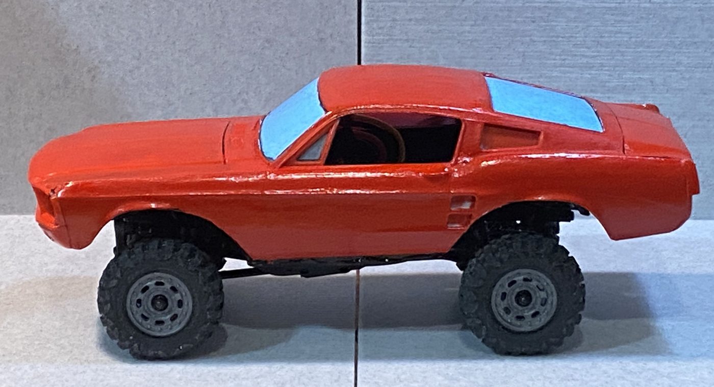
Hunt small cars. Japanese, European and pre-war American designs have short wheelbases. Post-war American cars mostly don't fit — the Mustang above is a fairly typical example, not an unlucky one.
The Willys is a truck and still worked: it's a 104″ pre-war car, so it's short despite the body style. Being a truck doesn't help or hurt; being short does.
The same trick covers the tail check. Real car's length ÷ scale must cover ~132 mm (the light-to-light number below). Almost everything passes with room to spare — it only gets close for very small cars. A kei car like the AZ-1 scales to ~137 mm, five millimetres from the line; anything tinier, run the division before buying.
Scale is a smaller lever than the car itself. The same Willys at 1/24 would come out at 110 mm and fail like the Mustang — so 1/25 helped, but only by about 4 mm. Choose the car first, the scale second.
An AI assistant handles this whole check well — and it's the fastest way to run it while standing in a shop. Tell it the car, the kit scale, and the target: "1940 Willys pickup, 1/25 scale — does the scaled wheelbase land near 99 mm?" It looks up the spec, does the math, and in our experience its fit predictions have been fairly reliable; our first successful build was an AI suggestion.
Even easier: just photograph the box. Most current assistants read images — snap the kit box and ask "would this fit a chassis with a 99 mm wheelbase?" It identifies the car and the scale off the box art and runs the whole check, no typing. (Not every AI handles photos, but most of the current ones do.)
Wheelbase you can derive; width you usually can't — but many retail listings publish the assembled dimensions. Amazon and most hobby shops print length and width in the product details, and that's the same number you'd measure. Worth thirty seconds before ordering.
Compare the listed width against the ~67 mm across our wheels. A body much wider than that swallows the wheels. The Tamiya 934 above lists 83 mm — 16 mm of overhang, and you can know that without opening anything.
Narrower than 67 mm is fine — the wheels simply stand slightly proud of the bodywork, which on a crawler reads as a wide stance rather than a mistake. The MGB scales to about 63 mm and looks right. It's the other direction that hurts: the Tamiya 934 at 83 mm buries the wheels 16 mm inside the body line.
This test only predicts one thing. Wheelbase tells you about arch alignment. It says nothing about rear deck height, body width, or a pointed nose — and any of those can still rule a kit out. Use it to reject bad candidates cheaply, not to confirm good ones.
The frame's own dimensions don't matter for fit — what matters is the chassis envelope: the hardware your body has to swallow. Three numbers cover it.
| Number | What it is | What it decides |
|---|---|---|
| 99 mm | Wheelbase, axle to axle | Whether the arches line up with the wheels. The only one you can check before buying — see the wheelbase test above. |
| ~67 mm | Across the wheels, outer wall to outer wall | Whether the wheels sit inside the body line or stand proud of it. A body much wider than this swallows the wheels and looks wrong. |
| ~132 mm | Front of the front light housing to the outer face of the rear light housing | Whether the tail clears. A body shorter than this runs into the rear light housings and needs cutting back there. |
Measured with calipers, rounded for use. Treat them as minimums with a little margin rather than exact targets — if your body is within a millimetre of any of these, assume it needs work.
One table, everything we know. Built = physically converted and driving. Dropped on = set on the chassis to check the geometry — promising, but not proof.
| Kit | Wheelbase check | Status | Verdict & notes |
|---|---|---|---|
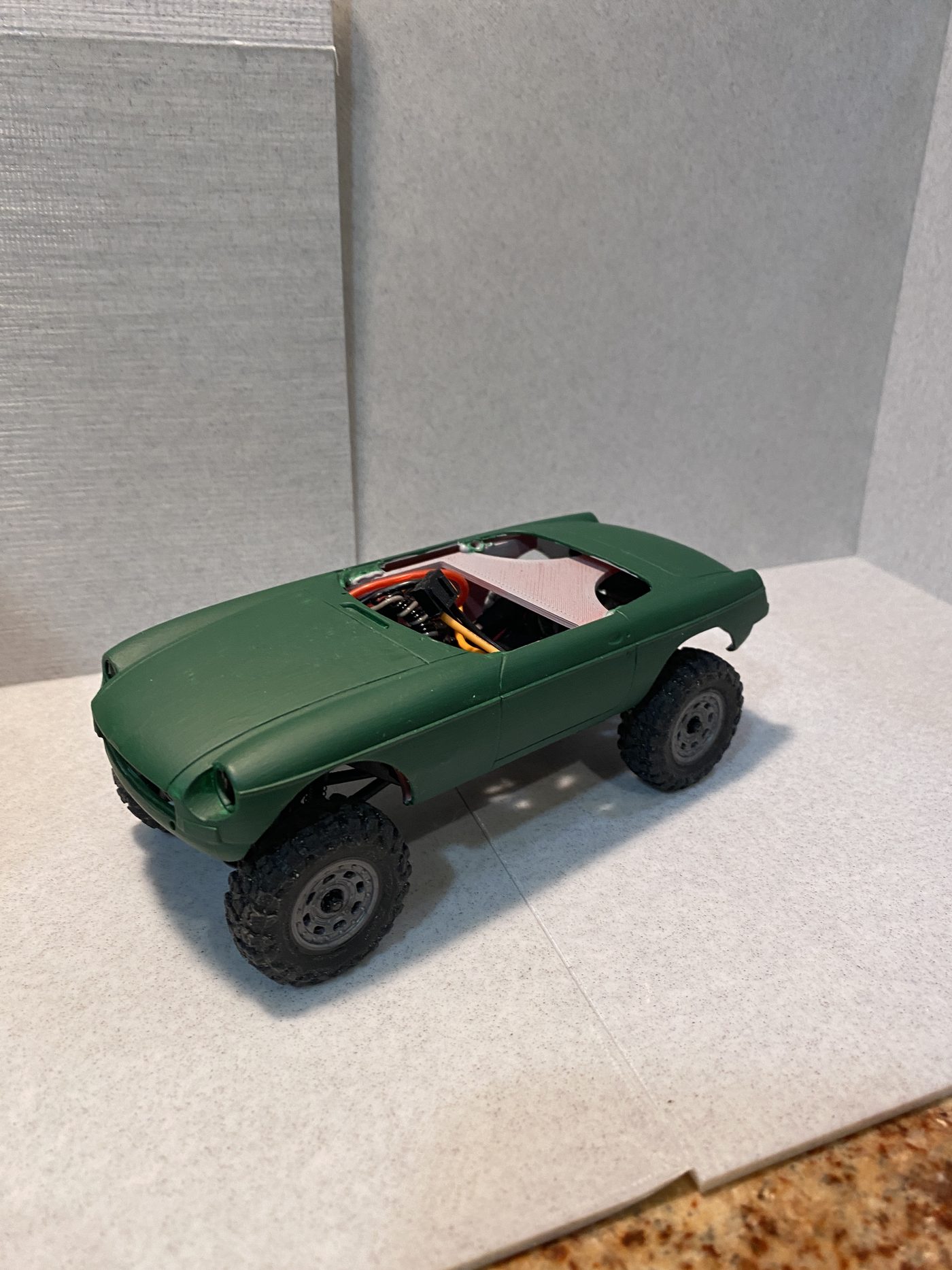
| Aoshima MGB ’68, 1/24 | 96 mm (−3) | Built — short shell | Best fit yet. Needed no rear cutting — it sits slightly high, so the light housings pass under the boot. Arches still opened. |
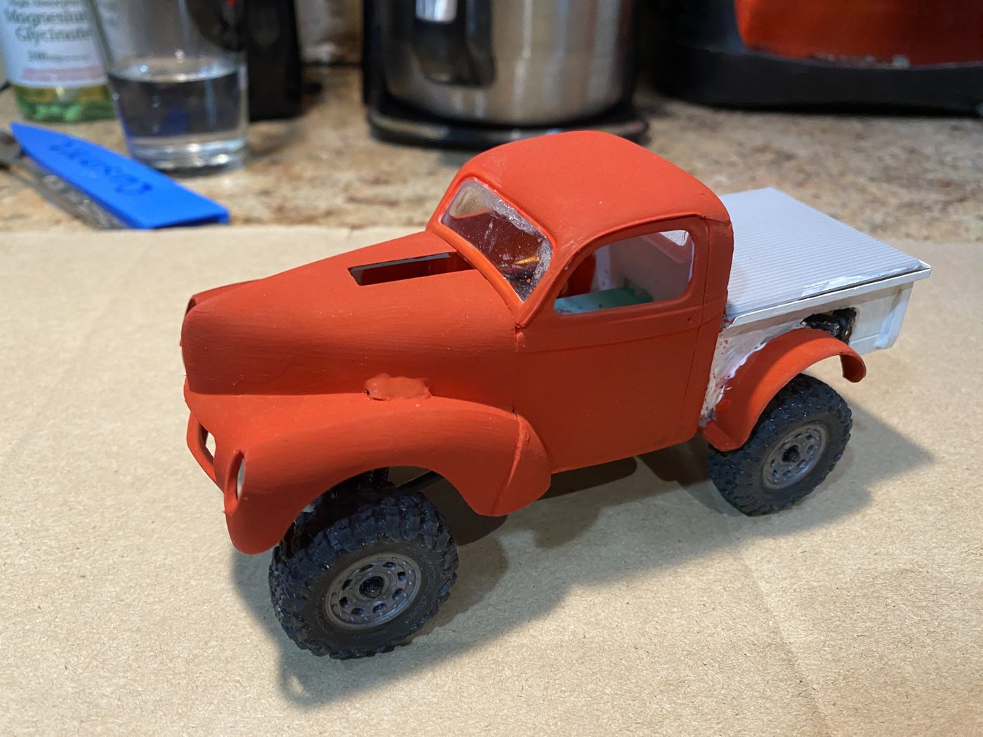
| AMT 1940 Willys Pickup, 1/25 | 106 mm (+7) | Built — spine rail | Works. The tail is real surgery — rear profiles and bed floor cut away to clear the light housings. Front and cabin straightforward. |
| AMT 1967 Mustang GT Fastback, 1/25 | 110 mm (+11) | Built | Goes on, looks poor — we wouldn't again. Arches never line up, and it rides a tyre-radius high (the only reason the tail cleared). |
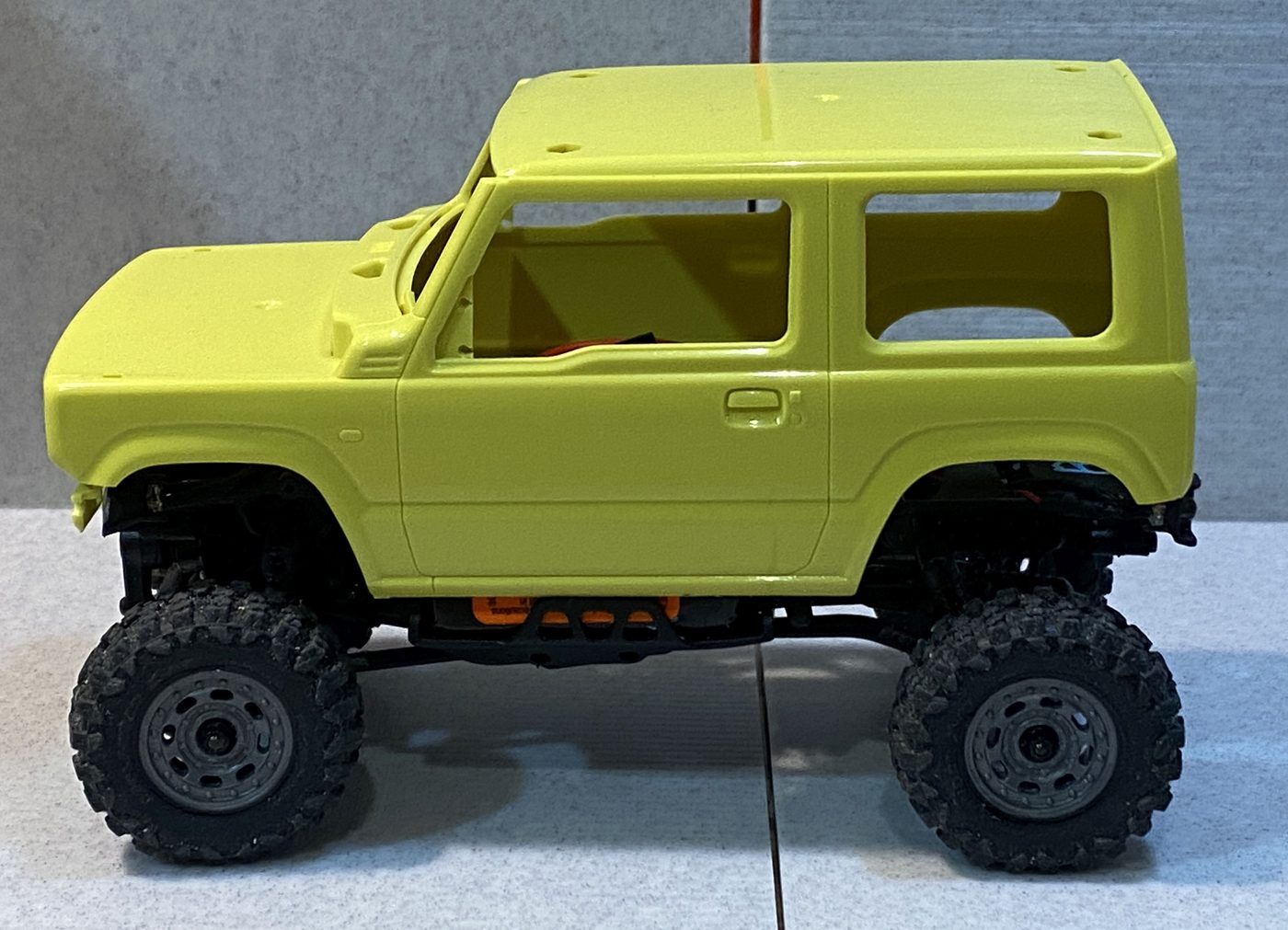
| Aoshima Suzuki Jimny, 1/24 | 94 mm (−5) | Dropped on | Promising — arches nearly line up as placed. |
| Mazdaspeed AZ-1 (kei), 1/24 | 93 mm (−6) | Dropped on | Promising, but shallow — little interior volume. The spine-rail recipe below is the likely route. |
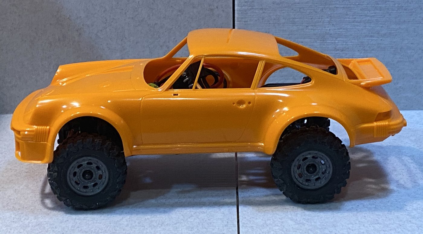
| Tamiya Porsche 934, 1/24 | 95 mm (−4) | Dropped on | Wheelbase is fine — width isn't. It's a racing wide-body, 83 mm against our 67 mm track, so the wheels sink deep inside. A standard-width 911 would fit better. |
The pattern in the table: Japanese and European subjects land inside tolerance; 60s American ones don't. Not listed doesn't mean it won't fit — it means we haven't tried it. Use the numbers above.
The bodies below are simply set on the chassis — nothing cut, nothing mounted, no arches opened. That's the raw starting point, and it's the fastest way to see whether a kit is worth the effort. All four are photographed the same way so you can compare them directly.
Look at two things first: where the wheels sit inside the arches, and how far the body floats above the tyres.
Then check two more that a side-on photo won't show you:
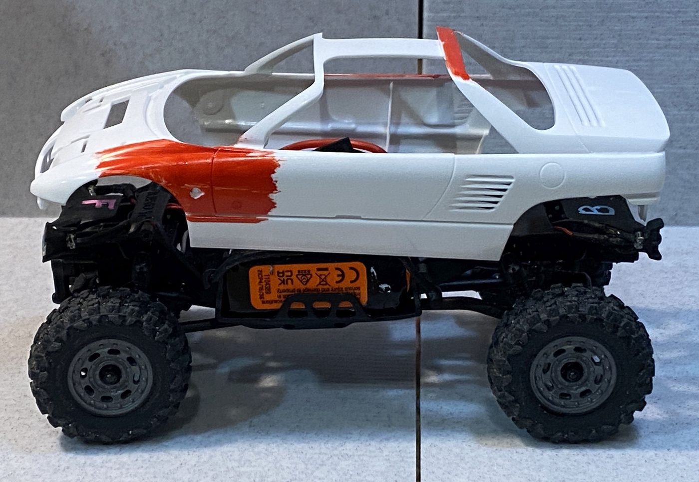
Shallow bodies aren't automatically disqualified — cutting often rescues them. If the body sits low and there's no interior volume to hide the frame, the recipe is: use the spine rail (the smallest thing you can put inside), cut relief where the front plank lands, and open the tail so the rear light housings tuck inside the body's volume instead of pushing it up from behind. Not a guarantee — but it works more often than not, and even when the fit stays imperfect, those cuts usually improve how the body sits.
No verdicts on the unbuilt ones. Three of the four above haven't been cut or mounted, so we're not claiming they work — only showing the starting point. A promising drop-on is where the work begins, not proof it will succeed.
Kits are listed by body, not by livery. The same tooling gets reboxed with different graphics and licensing — the plastic underneath is identical, so any boxing of the same kit fits the same way. Buy whichever version you like the look of.
Brand names appear here only to identify kits. Not affiliated with, sponsored by, or endorsed by any kit manufacturer.
| Version | Contains |
|---|---|
| Spine rail | Centre rail, complete — rear hook part of the print |
| Short shell | Short shell, complete — rear hook already fitted |
| Long shell | Long shell · rear hook loose — you position it (see below) |
| Enclosed platform | Enclosed platform, complete — rear hook already fitted |
| Platform kit | Spine rail + short shell + long shell — the three open sizes |
| Complete kit | Everything: all four versions in one box |
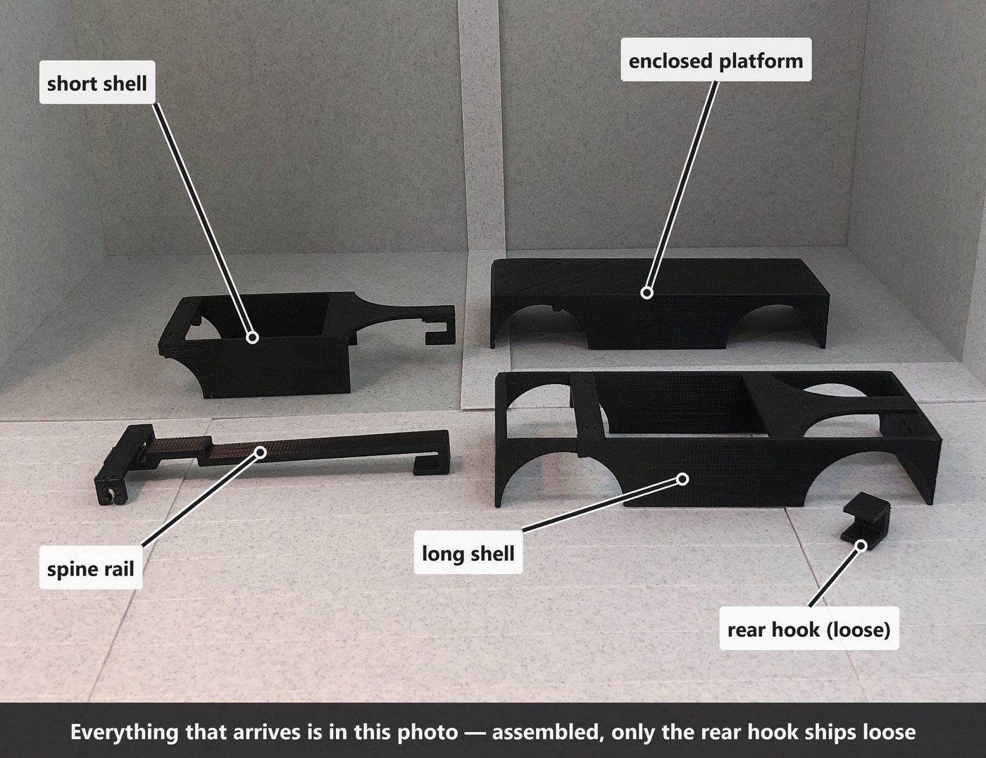
Whichever version you ordered, everything arrives assembled and ready to use. The only loose piece in any box is the long shell's rear hook.
The rear hook, per version: on the spine rail it's part of the print. On the short shell and the enclosed platform it arrives already glued — there's only one sensible position, so we do it before shipping. Only the long shell ships with the hook loose, because there it's a real decision: where you glue it sets whether the shell stays full-length or can later be cut down. See below.
| Tool | For |
|---|---|
| Rotary tool — sanding drum + abrasive cut-off disc | The drum opens wheel arches; the disc makes the big body cuts. If you're fitting a kit body, treat the drum as required — see below |
| Razor saw / fine-tooth hobby saw | Cutting the shell |
| Flush cutters | Trimming small parts |
| Hobby knife | Cleanup |
| Hand files | Tidying cut edges at the end |
| CA or E6000 / contact cement | Gluing — see below, the wrong glue won't hold |
Saw — don't snap. The shell is 3D printed, and printed plastic splits along its layer lines. A scored-and-snapped cut will crack somewhere you didn't intend.
Cut slowly with a sharp saw. A worn or coarse blade will grab and break the part. If you don't own a razor saw, use the short shell instead — that's exactly why it exists.
Model cement will not work. Plastic kit bodies are polystyrene, and modellers' styrene cement bonds styrene to styrene — it does nothing to the PLA our parts are printed in.
CA gel is what we actually use, for nearly everything. Not thin CA — gel. Three reasons:
In many cases the gel bead alone is the whole attachment — its thickness provides exactly the volume needed between frame and body, nothing else. Attachment is very body-specific, but on our builds plain gel covered most of it.
E6000 or contact cement work too, and stay slightly flexible — worth considering on a large glue area. Either way, scuff both faces first; glue grips a scratched surface far better than a smooth printed one.
CA accelerator (kicker) cures the glue instantly, so you can hold a part for two seconds instead of two minutes and move on. On a build with this many small joints it saves real time.
Most accelerators cause blooming — a chalky white haze that settles around the joint as the glue flash-cures. On bare plastic it's a nuisance you can polish off. On a painted body it's very visible and very annoying, and by then the paint is already on.
Not all of them do it. The one we use is a small bottle from a craft store — it smells oddly sweet, and whatever is in it seems to prevent the whitening entirely. Test yours on a painted offcut before you use it anywhere that shows.
Two habits that reduce blooming whatever you're using: apply the accelerator to one surface and let it flash off before bringing the parts together, rather than spraying it onto wet glue — and don't flood the joint. Bloom comes from excess vapour, so less glue means less haze.
Where the frame sides don't quite reach the body sides, glue alone makes a weak joint: it's bridging air, and it'll pop under the first knock. Put something in the gap instead.
On the paper body we used strips of cardboard packed between the body sides and the frame sides. Card is ideal for a paper body — same material, same thickness family — but almost anything with the right thickness works: scrap styrene, a sliver of shell offcut, thin craft-store wood planks (they cut with scissors and have real stiffness), toothpicks, coffee stirrers, a piece of drink straw. The shim is invisible — thickness is the only spec. Then glue to a shim that's actually touching both sides.
Apply CA sparingly around the front mount. CA wicks — gel much less than thin, which is another reason to use it. Glue that creeps into flexible sections makes them brittle, and they'll snap later under a load they should have survived.
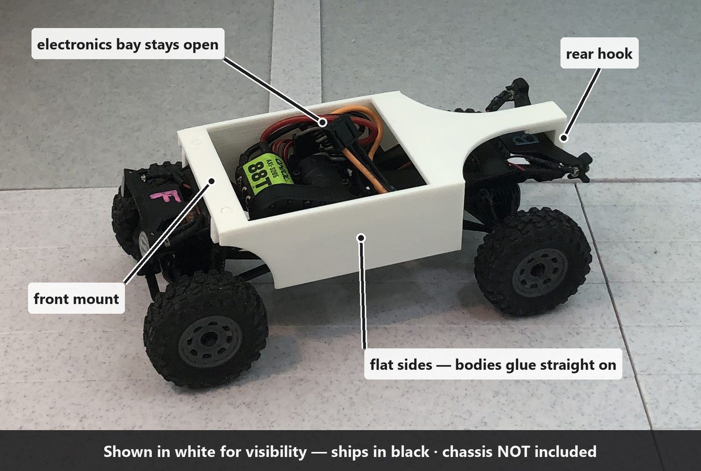
Three lengths, one interface. All of them mount the same way at both ends.
Each of the builds below is a real one, on the version named.
Fendered vintage bodies, narrow hoods, shallow low-volume bodies, scratch-builds — anything where you want as little as possible imposed on the body. It needs only a slot around the front plank rather than having to swallow a whole frame.
Shorter bodies. This isn't a cut-down long shell — it's its own, deliberately minimal design: it stops right after the rear support plank and carries no rear arches at all. Nothing to cut, no tools needed.
Full-size bodies. Can be cut down yourself if you have the saw.
For building something on top rather than fitting a body over. It closes the deck and seals the electronics underneath.
Cutting is one-way. The long shell trims anywhere between the back wall and the rear support plank — usually a cut through the middle of the rear arches is as far as you'll ever need to go — and it's also where cutting is easy, because you're only sawing the thin arch section. Going all the way down to the short shell's form is possible but awkward: at the rear plank the sides are full height, so it's a long cut through much more material that's hard to keep straight — and the plank itself sits right where you need to saw, blocking a clean stroke. If that's the length you want, buy the short shell. Either way, once cut it's never long again. If you want both lengths, you need both shells.
The other versions arrive with the hook already in place (or printed in). If you bought the long shell, read on.
Read this before gluing anything. This decision is permanent.
Where the hook sits isn't a choice. The spacing between the front plank and the hook is what the chassis expects — the hook's seat under the tail fixes it, and the locating pins mean it can't go on crooked. The decision is what to glue it to:
| Glue | Result |
|---|---|
| Under the deck only (glue 1 in the diagram) | The rear section stays removable — snap the break joint and trim whenever a body needs it. |
| Deck + back wall (glues 1 and 2) | Full-length, permanent, strongest. The rear never comes off cleanly again. |
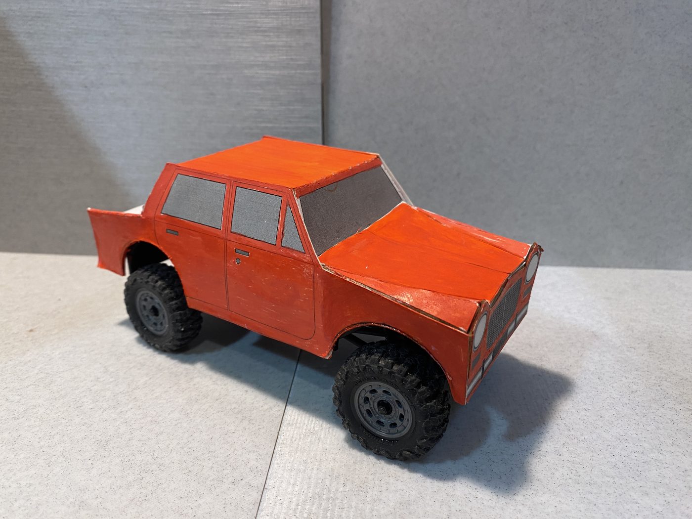
The body makes this call, not preference. Test-fit first: if the body has the inner room to swallow the back wall, keep the wall and glue both — the wall can even earn its keep as an extra attachment point. A boxy body sits right against it, so the body's rear can glue to the wall, shimmed to thickness if there's a gap; the paper car does exactly this.
If the body hasn't got that room, glue the deck only and take the rear off — or the short shell was the right part all along.
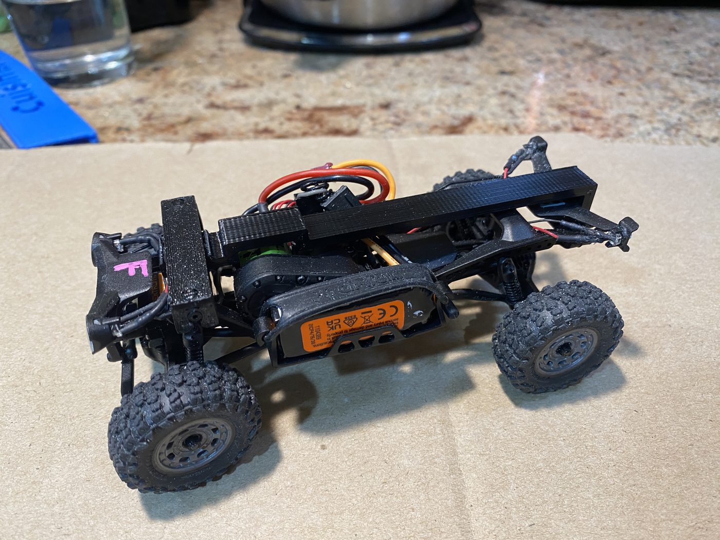
The frame goes on and comes off the same way as the stock body — the motions you already use for a battery change. Nothing else comes off the chassis, and no tools are involved.
Only if you're trimming a long shell. The short shell needs none of this — it's printed to its final shape.
The shell has fine scribed lines moulded into it marking where to cut. There's no measuring to do — the lines are the guide. They are cut guides, not score-and-snap lines. See the saw warning above.
Expect to cut the body. On most kits the interior has locating pins, floor pans and detail moulding that has to come out before the body will drop over the frame.
On most kit bodies this is the longest job — though not all of them need it. The chassis's rear light housings cause two separate problems:
On the Willys that meant losing the moulded rear profiles and the bed floor entirely.
The rear cut is the price of sitting low. Both bodies that needed no rear surgery avoided it the same way — by sitting high enough for the housings to pass underneath. The MGB sits slightly high and gets away with it. The Mustang sits far too high, which is exactly why it looks wrong.
So "no cutting needed" is not automatically good news. If a body clears the housings without work, check why — it may be telling you it's riding too tall.
We do this first — there's no point opening arches or trimming an interior on a body that turns out to sit 5 mm too high at the back.
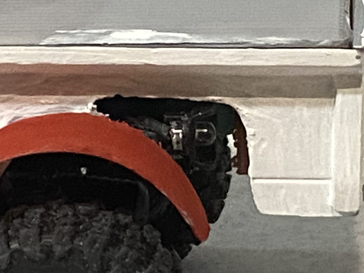
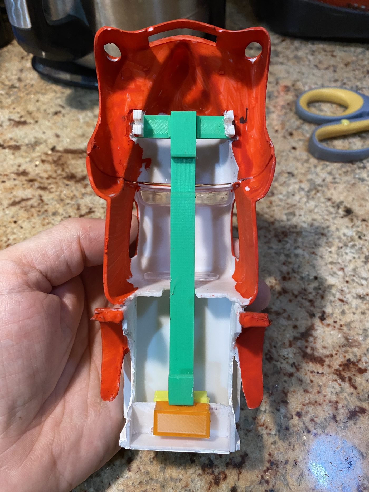
The front socket plank has to sit high enough to do its job, and on most bodies the underside of the hood is in the way. If you don't clear it, the body can't drop far enough and you're back to the floating-too-high look.
The fix is to cut through the hood where the plank lands. On the Willys that meant two holes in the hood — after which the body finally sat low enough to look right.
This is the one place where our part is the obstruction, not the chassis. And you can't avoid it by picking a different version — the spine rail has a front plank too. It's narrower, so it needs a smaller opening, but it still needs one.
A low, pointed nose is the hard case. Where the hood tapers to a narrow point, even the rail's slimmer plank can be wider than the space available. If that's your body, check this first — it can be the thing that rules a kit out entirely.
Style the cut rather than hiding it. Holes in a hood are what bonnet vents, scoops and louvres look like anyway. A cut you shaped deliberately reads as a design choice; a ragged one reads as damage. Same hole, different impression.
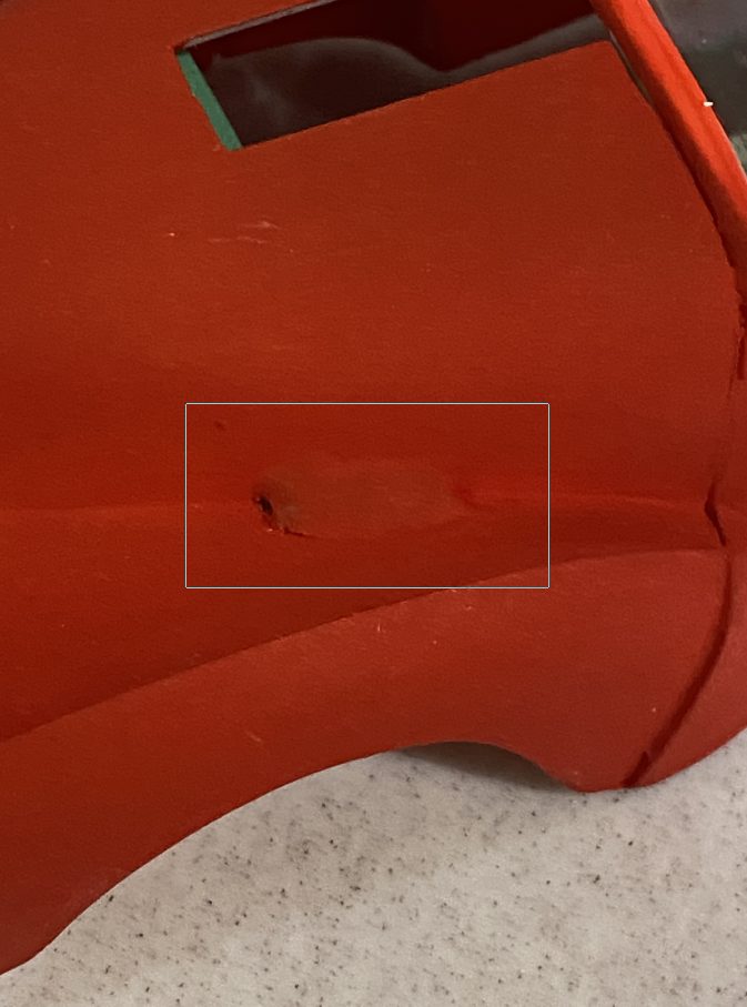
Paint after you cut, not before. A relief hole with a raw plastic edge and a bit of black plank poking through is obvious. The same hole painted over in body colour stops reading as damage and starts reading as panel detail. That's the cheapest fix in this whole guide.
Two more tricks from our builds. A bead of CA gel over the plank's exposed edge, dressed later with a Dremel, tidies where it shows through the hood — the boxed spot in the photo above is exactly this. And the plank's corners can be sanded back if they're what's in the way — no big deal, as long as the plank survives as a whole.
This is the job you will do on essentially every kit body, so it's worth having the right tool before you start. Crawler tyres are much larger relative to the body than the wheels the kit was designed around, so the arches have to be cut back until the tyre clears at full suspension travel.
Use a rotary tool with a sanding drum. The drum's diameter roughly matches the curve you're cutting, so it follows the arch naturally instead of fighting it — you sweep along the opening and the shape stays smooth. A knife leaves facets and chatter, and files are slow and hard to keep symmetrical.
Take material off in passes and offer the wheel up repeatedly. You can always remove more; you can't put styrene back.
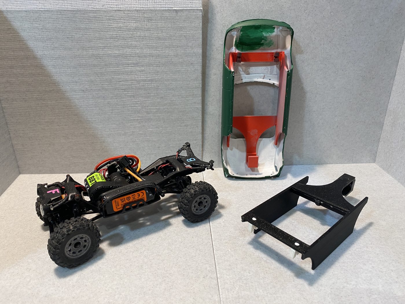
Paper is a good material here: near-zero weight, no glue chemistry problems, and you can make a new one next weekend.
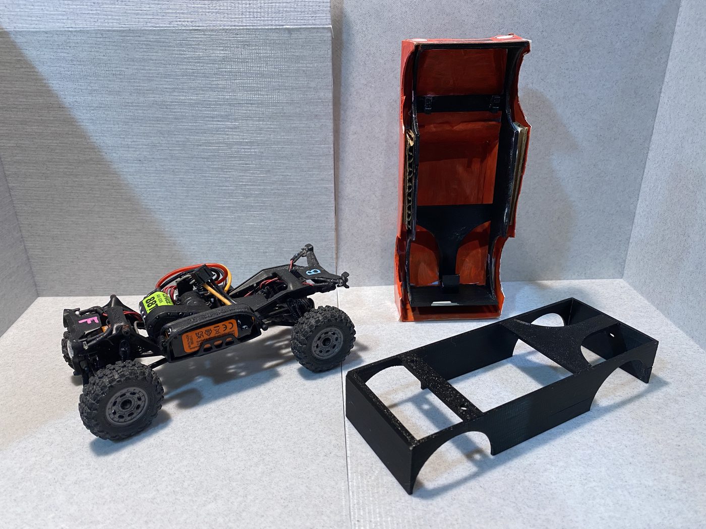
Attachment: CA again — thin and gel both earned their place here. The gap between the frame's sides and the paper body's sides gets cardboard strips as filler: the body's sides glue to the strips, and the strips glue to the frame's sides. Card suits a paper body — same material family — and it's the same shim trick from the glue chapter.
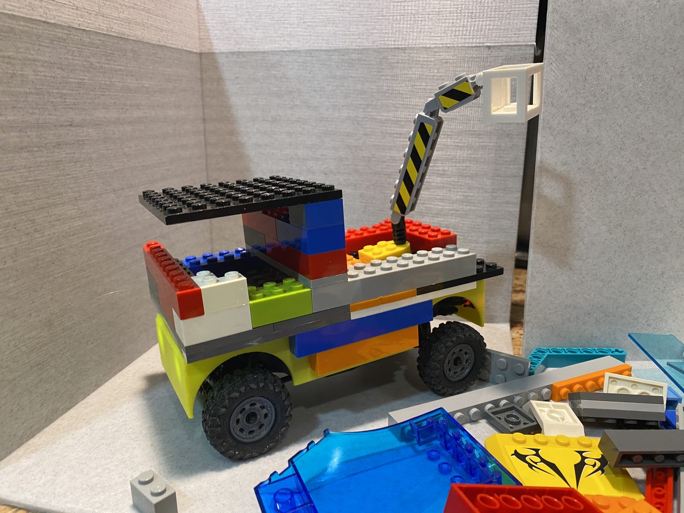
The enclosed platform closes the top and seals your electronics underneath, giving you a flat deck to build on. What you build is entirely up to you — glue a base plate on and it's a brick platform; glue something else on and it's something else.
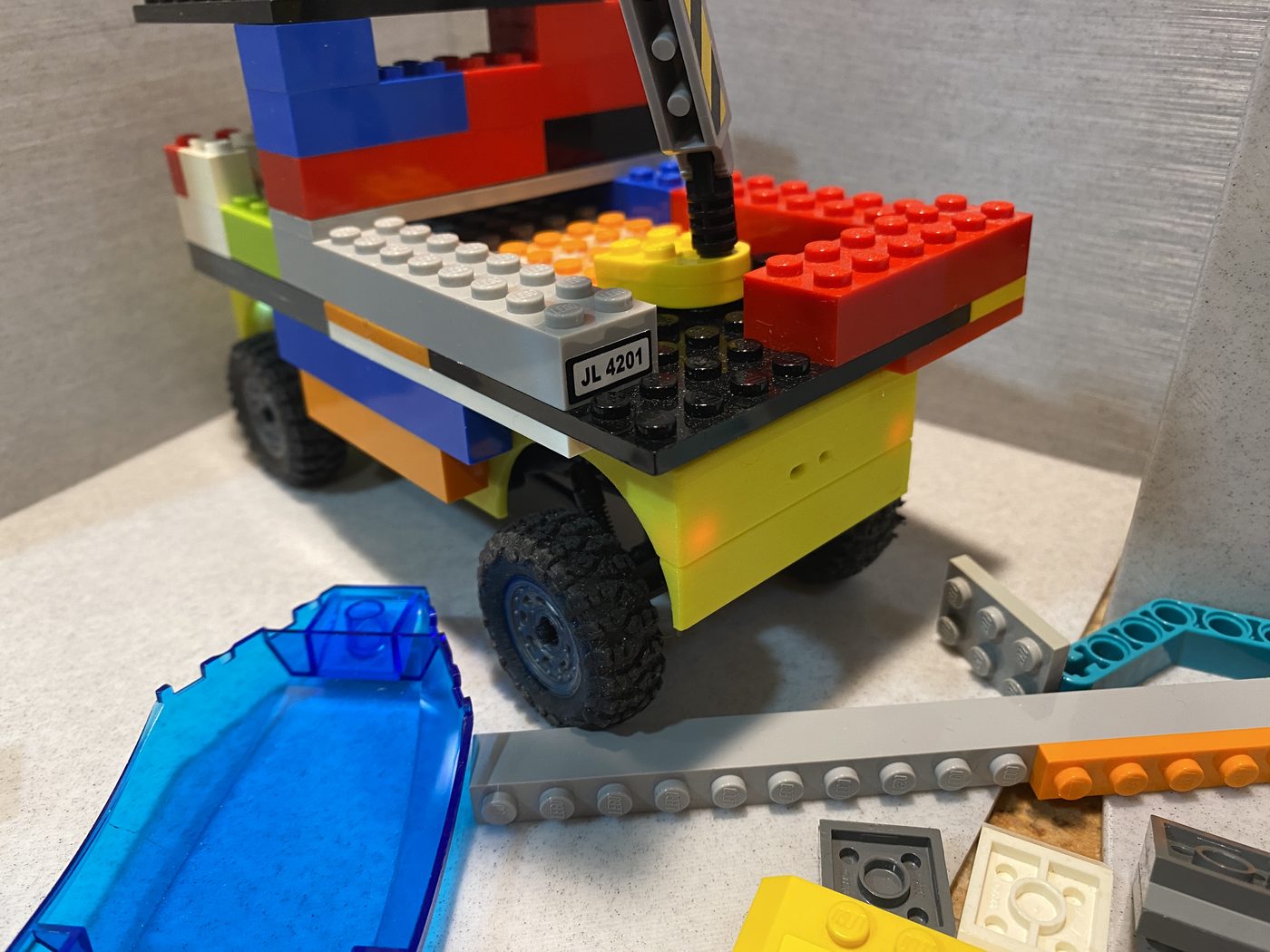
Keep your build low. The chassis is small and weight up high tips it nose-down and hurts how it drives. Building bricks in particular are heavier than they look.
The deck isn't a brick-standard width — the chassis is 77 mm wide, which doesn't divide into brick units. A base plate fits fine; the studs just won't sit symmetric to the deck edges — decide which side carries the offset before the first row.